How Does a Reducing Nipple Improve Flow Efficiency in Stainless Steel Pipe Systems
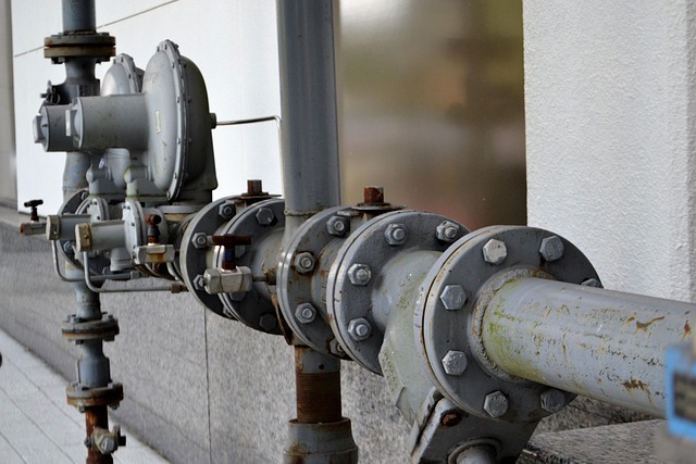
Stainless Steel Pipe Fitting, Hex Reducing Nipple, 3/4 in.
A stainless steel hex reducing nipple, particularly in a 3/4‑inch size, serves as a compact connector that allows two pipes of different diameters to join securely. This fitting is favored in industrial and commercial piping systems for its corrosion resistance, pressure endurance, and precision threading. The design minimizes the need for multiple adapters while maintaining consistent flow performance. In high‑pressure or corrosive environments such as chemical processing or marine applications, this component ensures a stable connection with minimal leakage risk.
Definition and Structural Characteristics
In stainless steel piping networks, a reducing nipple functions as a direct male‑to‑male threaded connector that transitions between two different pipe sizes. Its geometry is simple but highly functional, providing both strength and compactness.
A Reducing Nipple Is a Short Piece of Pipe with Male Threads on Both Ends
The primary purpose of this fitting is to connect pipes of differing diameters while maintaining thread integrity on both ends. The male threads are typically tapered to form a tight seal when engaged with matching female threads.
Typically Made from Stainless Steel for Corrosion Resistance and Durability
Grades such as 304 and 316 stainless steel are widely used because they resist oxidation and pitting even when exposed to moisture or chemicals. These alloys offer long service life in harsh conditions without the need for frequent replacement.
The Design Allows Seamless Transition Between Varying Pipe Sizes Without Additional Fittings
By combining reduction and coupling into one part, the nipple reduces potential leak points. This simplicity also saves installation time and space in confined mechanical rooms or under equipment skids.
Material and Manufacturing Considerations
The performance of a reducing nipple depends not only on its material but also on how precisely it is machined. Even small deviations can affect sealing performance or cause turbulence inside the pipeline.
Stainless Steel Grades Such as 304 and 316 Are Commonly Used for Their Mechanical Strength and Chemical Resistance
Grade 304 suits general industrial use where moderate corrosion protection suffices, while grade 316 includes molybdenum for superior resistance against chlorides found in seawater or chemical plants.
Precision Threading Ensures Leak-Free Connections Under High Pressure
Threads must conform to standards like ASME B1.20.1 (for NPT) or ISO 7/1 (for BSPT). Accurate threading prevents galling during assembly and keeps joints tight even under vibration or temperature changes.
Manufacturing Tolerances Directly Affect Flow Dynamics and Connection Integrity
If internal bore alignment deviates beyond tolerance limits, flow disturbances occur at the transition zone. Precision machining thus maintains both hydraulic efficiency and mechanical reliability over long-term operation.
The Role of Reducing Nipples in Flow Optimization
When fluid moves through a changing diameter section, its velocity and pressure shift according to fluid mechanics principles. A well‑designed reducing nipple helps manage these changes smoothly.
How Diameter Transition Affects Flow Dynamics
A gradual reduction minimizes turbulence at the junction point. Abrupt changes can cause eddies that waste energy and increase wear on downstream components such as valves or gauges.
Properly Designed Nipples Maintain Laminar Flow, Reducing Energy Losses
Maintaining laminar flow lowers pumping energy requirements across long pipelines. In systems carrying viscous fluids like oil or glycol mixtures, this effect becomes more noticeable.
Incorrect Sizing or Abrupt Transitions Can Cause Cavitation or Pressure Drops
Cavitation occurs when local pressure falls below vapor pressure due to sudden acceleration through narrow sections. This leads to noise, vibration, and surface erosion inside fittings if not properly sized.
Influence on Pressure Distribution and Velocity Profiles
Pressure distribution defines how evenly force acts along the pipeline walls. Smooth transitions help maintain predictable behavior across varying loads.
Reduction in Cross-Sectional Area Increases Fluid Velocity According to Continuity Principles
As area decreases, velocity rises proportionally to maintain mass flow rate consistency—an essential relationship described by Bernoulli’s equation used widely in engineering design.
Controlled Acceleration Helps Maintain Consistent Pressure Gradients Across the System
By designing an appropriate taper length within the nipple’s bore, engineers can balance acceleration so that downstream instruments experience stable readings without pulsation effects.
Optimized Nipple Geometry Prevents Backflow and Vibration Issues in High-Speed Systems
In high-speed gas lines or pump discharge outlets, poorly shaped reducers can trigger resonance vibrations; refined geometry eliminates these risks while keeping noise levels low.
Integration of Reducing Nipples into Stainless Steel Pipe Networks
Integration requires attention to compatibility among threads, materials, and sealing compounds to avoid galvanic corrosion or leaks over time.
Compatibility with Other Fittings and Components
Thread types such as NPT (National Pipe Taper) or BSPT (British Standard Pipe Taper) dictate interchangeability within regional systems. Mismatched standards often lead to cross-threading problems during assembly.
Use of Thread Sealants or PTFE Tape Ensures Tight, Corrosion-Resistant Joints
PTFE tape fills microscopic gaps between threads while resisting chemical attack from most fluids handled by stainless steel systems.
Integration Must Consider Thermal Expansion Coefficients Between Connected Materials
When connecting stainless steel nipples to other metals like brass or carbon steel, differing expansion rates under heat cycles can loosen joints unless compensated by flexible couplings or thread sealants rated for temperature variation.
Installation Best Practices for Flow Efficiency
Installation affects both performance and longevity; improper torque or misalignment may negate even high-quality manufacturing advantages.
Proper Alignment During Installation Prevents Misthreading and Internal Surface Irregularities
Using alignment tools ensures threads engage smoothly without cross-cutting metal surfaces that could trap debris later during operation.
Torque Specifications Should Be Followed to Avoid Over-Tightening or Leakage
Manufacturers specify torque ranges based on thread type; exceeding them risks cracking thin-walled fittings while insufficient torque causes micro-leaks under pressure testing conditions defined by ISO 5208 standards.
Routine Inspection Ensures No Buildup or Corrosion at the Transition Point That Could Hinder Flow Efficiency
Periodic visual checks detect mineral deposits early before they restrict passage area; cleaning schedules depend on medium type—water systems may require quarterly inspections versus annual checks for gas lines.
Engineering Advantages of Using Reducing Nipples in System Design
Beyond basic connectivity, these fittings contribute structural simplicity that benefits layout planning across industries from HVAC installations to petrochemical transport lines.
Space-Saving and Simplified Configuration Benefits
Replacing separate reducer-coupling assemblies with one piece frees space around manifolds where clearance is limited by insulation layers or adjacent piping runs.
Reduces Potential Leak Points by Minimizing Joint Count
Every joint represents a possible failure site; fewer connections translate directly into lower maintenance frequency over system life cycles measured in decades for stainless assemblies.
Simplifies Maintenance by Allowing Direct Replacement Without Major Disassembly
Technicians can remove worn nipples using standard wrenches without disturbing neighboring flanges—a practical advantage during shutdown periods when downtime costs escalate quickly.
Contribution to System Longevity and Maintenance Efficiency
Durability remains central because downtime expenses often outweigh hardware cost differences between materials like brass versus stainless steel.
Stainless Steel Construction Resists Wear from Fluid Friction and Chemical Exposure
Continuous exposure to moving fluids gradually erodes softer metals; stainless alloys maintain dimensional stability even after years of service under abrasive slurry conditions common in process industries.
Smooth Internal Surfaces Reduce Scaling, Promoting Consistent Flow Rates Over Time
Polished finishes discourage deposit accumulation inside pipelines conveying hard water solutions containing calcium carbonate particles that otherwise form scale layers reducing effective diameter.
Ease of Disassembly Supports Periodic Cleaning or System Reconfiguration Without Significant Downtime
Quick removal capability allows engineers to modify network layouts when production demands change—especially valuable in modular plant designs where flexibility matters more than initial cost savings.
Evaluating Performance Parameters for Optimal Selection
Selecting the correct reducing nipple involves balancing hydraulic needs with material compatibility under expected operating conditions defined by project specifications.
Criteria for Choosing the Right Reducing Nipple Size and Type
Flow rate determines appropriate diameter ratio between inlet and outlet sections; engineers calculate this using volumetric formulas tied to pump capacity ratings specified per ISO 9906 guidelines.
Operating temperature range also guides alloy selection since elevated heat can reduce tensile strength differently among grades 304 versus 316L variants designed for cryogenic service environments too.
Thread pattern must match existing infrastructure standard—mixing metric with imperial thread forms risks leaks even if dimensions appear similar visually.
Testing and Validation Methods for Flow Efficiency Assessment
Computational fluid dynamics (CFD) models simulate velocity profiles within transition zones before fabrication begins; results reveal whether redesign adjustments are needed prior to production approval stages governed by ASME B31 process codes.
Pressure drop measurements taken during commissioning confirm theoretical predictions align with field data collected via calibrated differential manometers placed upstream/downstream of each fitting location.
Periodic field testing validates continued efficiency after extended exposure cycles ensuring no internal corrosion pits have formed affecting laminar characteristics critical for precision dosing systems used in pharmaceutical manufacturing lines.
FAQ
Q1: What is the main purpose of a reducing nipple?
A: It connects two pipes of different diameters using male threads on both ends while maintaining pressure integrity within stainless steel piping systems.
Q2: Why choose stainless steel instead of brass?
A: Stainless steel offers higher corrosion resistance especially against chlorides found in marine environments where brass would dezincify over time.
Q3: Can PTFE tape be used with all thread types?
A: Yes, but it should be applied following manufacturer instructions since excessive wrapping may distort thread engagement leading to leaks under high torque conditions.
Q4: How often should installed nipples be inspected?
A: For water-based media every three months is typical; gas applications may extend inspection intervals up to one year depending on service severity classification per ISO maintenance guidelines.
Q5: What happens if an incorrect size is installed?
A: Mis-sized fittings create abrupt flow transitions causing turbulence, cavitation damage, increased energy consumption, and potential failure at joint interfaces over time.


