What Causes Leaks in Compression Fitting Valves and How to Prevent Them
Common Causes of Leaks in Compression Fittings
Compression fitting valves are critical for maintaining the integrity of industrial fluid systems, yet leaks remain a recurring challenge. The majority of failures stem from improper installation, material mismatch, or long-term fatigue. When these valves leak, it’s rarely due to the component design itself but rather to human or environmental factors during assembly and operation. A well-installed compression fitting valve can last for years without issue, but one overtightened nut or misaligned tube can compromise an entire process line.
The Function and Design of Compression Fitting Valves
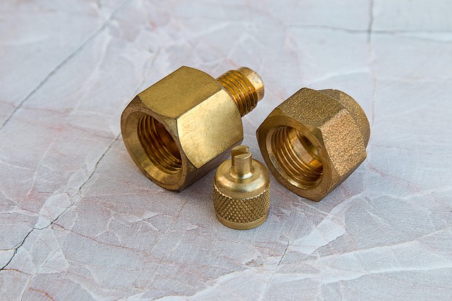
Compression fitting valves serve as essential connectors in pressurized systems where welding or soldering is impractical. They rely on mechanical compression to form a tight seal between metal surfaces.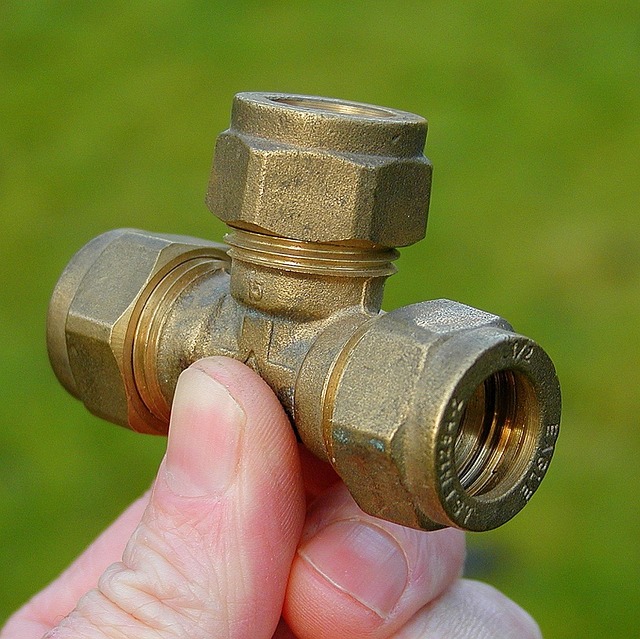
The Function and Design of Compression Fitting Valves
A typical compression fitting valve includes three main parts: the body, nut, and ferrule or ferrules. When the nut is tightened, it compresses the ferrule around the tubing, creating a seal that prevents leakage even under high pressure. This mechanical deformation is what gives these fittings their reliability in both static and dynamic systems.
Common Applications in Industrial Systems
These fittings are widely used in industries such as oil and gas, chemical processing, and hydraulic control. Their ability to handle high temperatures and pressures makes them indispensable in mission-critical environments like offshore rigs or laboratory gas lines. Maintenance teams favor them because they can be easily disassembled for inspection without cutting or re-welding pipes.
Primary Causes of Leaks in Compression Fitting Valves
Even with precision engineering, leaks occur when installation or maintenance practices deviate from standard procedures. Understanding these causes helps engineers identify weak points before system startup.
Improper Installation Practices
Improper torque application remains the leading cause of leakage. Over-tightening distorts ferrules and damages sealing surfaces, while under-tightening leaves gaps that allow fluid bypass. Misalignment between tubing and valve body also creates uneven pressure distribution along the sealing interface. In field conditions where speed often trumps precision, these small deviations quickly become costly failures.
Material Compatibility Issues
Material mismatches between tubing and fittings often trigger corrosion or galling. For instance, coupling stainless steel fittings with softer copper tubes can lead to surface abrasion during tightening. Temperature fluctuations worsen this by causing differential expansion between metals, loosening joints over time. In chemical plants, choosing incompatible materials can degrade ferrule integrity when exposed to aggressive media like acids or solvents.
Wear and Fatigue Over Time
Continuous vibration from pumps or compressors induces micro-movements at joints that gradually wear down contact surfaces. Repeated assembly cycles further weaken ferrules as their edges lose sharpness needed for proper grip. Thread damage from cross-threading also contributes to poor sealing performance during reinstallation.
Contamination During Assembly
Foreign particles trapped on threads or ferrules obstruct full metal-to-metal contact. Even small debris can create leak paths under pressure testing conditions. Residual lubricants from manufacturing processes interfere with frictional locking mechanisms within the fitting. Moisture ingress during storage accelerates corrosion at interfaces before installation begins.
Diagnostic Techniques for Identifying Leak Sources
Leak detection requires both visual assessment and quantitative testing methods to pinpoint root causes accurately.
Visual Inspection and Torque Verification
Technicians first inspect fittings for visible deformation marks or discoloration indicating over-compression. Using calibrated torque wrenches verifies that nuts were tightened within specified limits set by manufacturers like Swagelok or Parker Hannifin. Checking tube alignment ensures concentricity between components—a common oversight during field installations.
Pressure Testing Methods
Hydrostatic Testing Procedures
Hydrostatic testing involves filling the system with water and applying controlled pressure beyond normal operating levels to observe any visible leaks under static conditions. It’s a straightforward yet effective method for identifying gross defects before commissioning.
Helium Leak Detection Techniques
For high-integrity systems such as aerospace fuel lines or semiconductor gas delivery networks, helium mass spectrometry offers unmatched sensitivity in detecting micro-leaks invisible to conventional tests.
Strategies to Prevent Leaks in Compression Fitting Valves
Preventive strategies combine proper installation discipline with informed material selection and periodic maintenance routines.
Adhering to Proper Installation Protocols
Tube Preparation Standards
Tubing must be cut squarely using specialized cutters to avoid burrs that disrupt uniform contact surfaces inside the fitting body.
Controlled Tightening Procedures
Following manufacturer torque charts is crucial; technicians should apply consistent tightening angles rather than relying on subjective feel alone.
Selecting Appropriate Materials and Components
Matching Tubing and Fitting Materials
Material compatibility should reflect actual service conditions—temperature range, pressure rating, and fluid composition—not just procurement convenience.
Utilizing High-performance Ferrule Designs
Double-ferrule configurations enhance sealing redundancy by separating grip force from seal formation, reducing risk under cyclic loading conditions.
Implementing Regular Maintenance Practices
Scheduled Inspections
Routine checks detect early signs of corrosion or mechanical loosening caused by vibration exposure in rotating machinery zones.
Replacement Intervals
Worn-out ferrules should be replaced proactively rather than reused; even minor surface wear compromises long-term sealing reliability.
Advanced Engineering Solutions for Leak Prevention
Modern engineering introduces surface treatments and digital monitoring tools that extend valve life cycles beyond traditional expectations.
Surface Treatments and Coatings
Applying anti-galling coatings reduces friction during assembly while corrosion-resistant finishes protect against harsh chemicals common in refineries or desalination plants.
Integration of Monitoring Technologies
Smart sensors embedded near fittings monitor pressure differentials in real time, alerting operators before leaks escalate into safety incidents. Predictive maintenance software analyzes vibration data trends to forecast joint fatigue with remarkable accuracy—an emerging standard across process industries aligned with ISO 20815 asset management frameworks.
Best Practices in System Design to Minimize Leak Risks
Design philosophy plays a decisive role in minimizing leak probability throughout an installation’s lifespan.
Designing for Accessibility and Maintainability
Engineers should locate compression fittings where inspection tools can easily reach them without dismantling large assemblies—a principle often overlooked during compact skid designs.
Minimizing Vibration Transmission
Installing flexible supports near pumps or compressors isolates fittings from direct vibration transfer, significantly extending joint longevity under continuous operation cycles exceeding 10⁶ load reversals per IEC mechanical endurance standards.
FAQ
Q1: What is the most common reason compression fitting valves leak?
A: Most leaks occur due to incorrect tightening torque during installation rather than product defects.
Q2: Can reused ferrules maintain reliable seals?
A: No; reused ferrules lose their original geometry after compression, leading to uneven sealing surfaces upon reassembly.
Q3: How often should compression fittings be inspected?
A: High-pressure systems typically require inspection every six months depending on vibration exposure levels and fluid type handled.
Q4: Are double-ferrule designs always better than single-ferrule ones?
A: Double-ferrule systems provide superior grip under dynamic loads but may not be necessary for low-pressure static applications where simplicity suffices.
Q5: Do temperature changes affect sealing performance?
A: Yes; thermal expansion differences between tubing and fitting materials can gradually loosen joints if not properly matched during design selection.


