
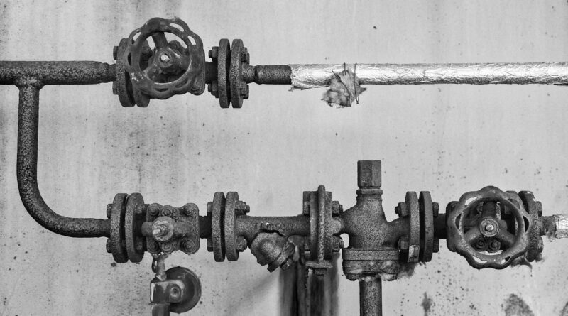
Tube valves and fittings selection for industrial fluid systems
Why tube valves and fittings should be selected as a system
Tube valves and fittings are small parts, but they have a direct effect on whether an industrial fluid system is safe, maintainable and resistant to leakage. Selection should begin with the actual service conditions: pressure, temperature, fluid media, vibration, cleaning requirements and maintenance access. Once those factors are defined, engineers can compare valve type, fitting geometry, tubing specification and material grade with a clear basis.
A reliable tube system is not created by choosing the strongest single component. The valve, fitting, tube, seal material and installation method all have to work together. A high-rated valve will not compensate for an incompatible seal, damaged tube end, unsupported line or fitting system assembled with mismatched parts.
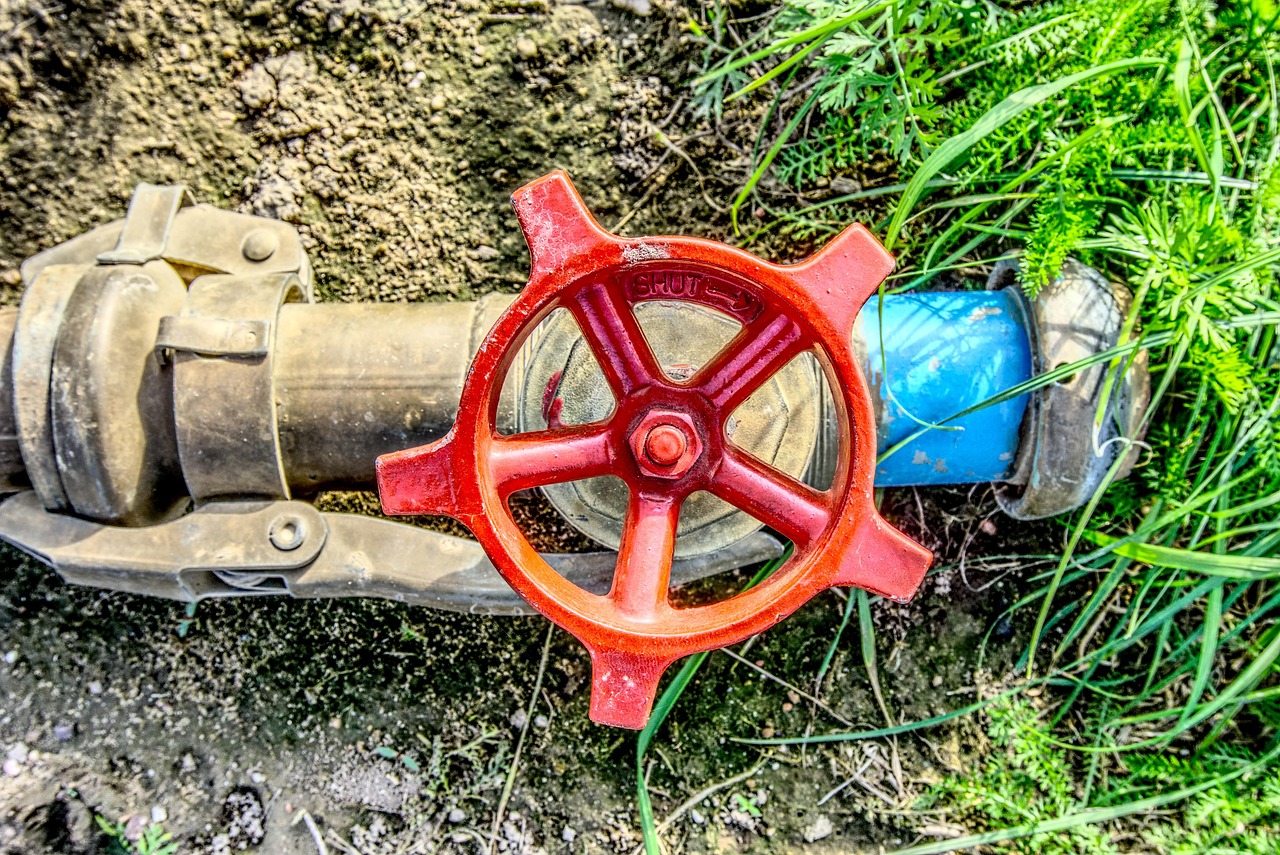
This guide explains the main choices behind tube valves and fittings for instrumentation, process, utility and small-bore fluid lines. It focuses on selection logic rather than brand claims, so the same framework can be applied across stainless steel, alloy, polymer and specialty tubing systems.
What tube valves and fittings do in a fluid system
Tube fittings create mechanical connections between tubing sections, instruments, manifolds, valves, regulators, filters and other components. Tube valves control what happens inside those lines: they isolate, meter, divert, prevent reverse flow, relieve pressure or provide sampling access. In compact assemblies, the fitting and the valve connection are closely linked because the end connection affects layout, leak paths, installation space and future maintenance.
Industrial tube systems are used in analytical lines, chemical dosing skids, hydraulic and pneumatic circuits, semiconductor utilities, laboratory gas panels, sampling systems, instrumentation impulse lines and compact process assemblies. These applications often use tubing rather than large pipe because tubing can be routed through tighter spaces and is commonly specified by outside diameter and wall thickness. Pipe is more often specified by nominal pipe size and schedule. That difference matters: a fitting designed for a specific tube outside diameter must also match the actual tube size, wall thickness and hardness range.
Common fitting families include compression fittings, bite-type fittings, face-seal fittings, flare fittings, weld fittings and threaded adapters. Common valve types include ball valves, needle valves, check valves, relief valves, diaphragm valves and manifold valves. No single style is correct for every service. A quarter-turn ball valve may suit quick isolation, while a needle valve is usually better for gradual flow adjustment. A check valve can help reduce reverse flow, but it should not be treated as a substitute for a formal safety design where pressure protection is required.
Start with service conditions, not the catalog page
The first selection step is to define the real operating envelope. That includes normal operation, startup, shutdown, cleaning, pressure testing and upset conditions. A component that appears suitable at ambient temperature may become unsuitable once seal limits, thermal expansion or corrosion exposure are considered.
| Selection factor | Why it matters | What to verify before ordering |
|---|---|---|
| Pressure | The system is limited by its lowest rated component, not by the strongest valve or fitting. | Maximum working pressure, test pressure, pressure spikes and any derating at temperature. |
| Temperature | Heat and cold can change seal performance, material strength and installation stress. | Continuous temperature, short-term peaks, cleaning temperature and ambient exposure. |
| Fluid media | Chemicals, gases, steam, hydraulic fluids and solvents can attack metals or soft seals in different ways. | Material compatibility, seal compatibility, concentration, moisture, oxygen and contamination risk. |
| Tube dimensions | Tube outside diameter, wall thickness and hardness influence grip, sealing and pressure capability. | Tube specification, tolerance, wall thickness table and compatibility with the fitting series. |
| Movement and vibration | Vibration can loosen poorly supported lines and increase fatigue risk near connections. | Clamp spacing, bend radius, tube support, equipment vibration and thermal movement. |
| Maintenance access | A theoretically sound layout can still fail in service if technicians cannot inspect or remake connections. | Wrench clearance, valve handle access, tagging, drain points and isolation procedure. |
Many field problems start with incomplete service data rather than an obviously wrong component. A stainless steel tube fitting may be acceptable for one water-based service but unsuitable for another if chloride concentration, temperature or cleaning chemicals change the corrosion risk. In the same way, a valve selected only by port size may create an unexpected pressure drop or leave too little room for operation after installation.
Match the tubing, fitting and valve connection
Tube connection performance depends on the relationship between the tube and the fitting. The tube must be round, clean, correctly cut and within the dimensional and hardness range expected by the fitting manufacturer. A damaged tube end, heavy burr, deep scratch or out-of-tolerance wall thickness can compromise sealing before the system enters service.
Compression-style tube fittings are widely used because they allow mechanical assembly without welding. Depending on the design, one or more ferrules grip and seal against the tube as the nut is tightened. These fittings are convenient, but they are not automatically interchangeable across manufacturers. Many product catalogs warn against mixing nuts, ferrules and bodies from different fitting systems because geometry, surface treatment and installation movement may differ. For maintenance teams, spare parts control is therefore part of leak prevention.
Welded connections reduce the number of mechanical joints and may be preferred where cleanliness, vibration resistance or permanent construction is important. Welding also adds requirements for procedure control, heat-affected zone quality, purge gas practice and inspection. Threaded adapters are useful when tube systems connect to instruments or pipe components, but threads bring their own concerns: sealant compatibility, galling risk, torque control and the possibility of over-tightening small components.
Valve end connections should be chosen with the same discipline. A valve may be available with tube ends, female pipe threads, male pipe threads, weld ends or face-seal ends. The best option is the one that reduces unnecessary adapters while still allowing installation, inspection and replacement. Every extra adapter adds cost, length, pressure drop and another potential leak point.
Standards and specifications that shape selection
Tube valves and fittings are often selected within a broader code or project specification. ASME B31.3 is commonly referenced for process piping in industries such as chemical, petroleum, pharmaceutical, hydrogen, power, semiconductor and cryogenic facilities. It does not replace the need to read the component manufacturer’s data, but it frames responsibilities for design conditions, materials, fabrication, examination and pressure testing in process piping applications.
For stainless steel tubing, ASTM A269 is a common specification for seamless and welded austenitic stainless steel tubing for general service. When a project calls for ASTM A269 tubing, the purchasing description should still identify grade, size, wall thickness, finish and any additional requirements. The standard name alone is not enough to confirm that a tube is suitable for a specific chemical, pressure or cleanliness requirement.
Other specifications may apply depending on the industry and connection style. High-purity gas systems, hydraulic circuits, sanitary process lines and offshore equipment may use different requirements for material traceability, surface finish, cleaning, pressure testing or documentation. Standards help define minimum requirements, but they do not make every valve and fitting suitable for every service. The actual design still has to compare the component rating with the fluid, temperature, pressure and installation method.
Material selection and corrosion risk
Material selection is more than choosing stainless steel by default. 316 and 316L stainless steels are common in instrumentation and process tubing because they provide broad corrosion resistance in many industrial environments. They are not immune, however, to pitting, crevice corrosion, chloride stress corrosion cracking or chemical attack. Carbon steel, brass, copper, nickel alloys, duplex stainless steel, PTFE, PFA and other materials may be suitable under different conditions. See also: Bolts & Fasteners.
The metal body is only part of the decision. Valve seats, stem packing, O-rings, diaphragms and lubricants must also be compatible with the fluid and temperature. A valve body may withstand a solvent while an elastomer seal swells, hardens or loses elasticity. In oxygen service, fuel gas service or high-purity applications, cleaning and lubricant selection can be as important as base metal strength.
Galvanic corrosion should also be considered when dissimilar metals are joined in the presence of an electrolyte. For example, mixing copper alloy components with stainless steel in a wet or outdoor environment can create corrosion concerns if the design does not account for the galvanic relationship, drainage and exposure. Material compatibility charts are useful starting points, but they cannot replace project-specific review where concentration, temperature, aeration and contamination vary.
Installation details that affect leak performance
Even correctly specified tube valves and fittings can leak if installation is poor. Good practice starts with tube preparation: cut squarely, deburr carefully, remove chips, inspect the outside surface and avoid flattening the tube in a vise or cutter. The tube should bottom properly in the fitting before tightening. If the installation instructions call for a specific nut rotation, gap gauge or torque value, that method should be followed rather than replaced by feel.
Tube routing is just as important. Long unsupported runs can vibrate. Tight bends can transmit stress into fittings. Heavy valves installed without support can load the tube connection. Thermal expansion can move a line enough to create stress at a rigidly mounted panel or manifold. These issues are not solved by simply choosing a higher pressure rating; they require better layout, support, clamping and allowance for movement.
Inspection should look beyond visible drips. Gas systems may require appropriate leak detection methods. Hydraulic systems may show residue before an obvious leak appears. Sampling and analytical systems may suffer from small leaks that affect measurement accuracy rather than create an immediate safety event. Documentation also matters: installers should know whether a fitting is new, previously assembled or being remade according to the manufacturer’s instructions.
A practical selection checklist for tube valves and fittings
The following checklist can help purchasing, maintenance and engineering teams align before components are ordered:
- Define the maximum and minimum pressure and temperature, including startup, cleaning and upset conditions.
- Identify the fluid media, concentration, phase, contamination risk and any cleaning chemicals.
- Confirm tube outside diameter, wall thickness, material grade, hardness range and applicable tubing specification.
- Choose the valve function first: isolation, metering, check, relief, sampling, venting or manifold control.
- Reduce unnecessary adapters by matching valve end connections to the tubing layout.
- Check the pressure rating of every component, including adapters, seals and threaded connections.
- Review corrosion risk, including chloride exposure, galvanic couples, outdoor service and trapped fluids.
- Confirm that installers have the correct tools, gauges, instructions and spare parts from the same fitting system.
- Allow room for valve operation, tube bending, wrench access, inspection and safe replacement.
- Document the final selection so future maintenance does not mix incompatible components.
Common mistakes include selecting by tube size alone, assuming all stainless steels behave the same, mixing fitting components from different systems, ignoring seal material limits and adding adapters after layout problems appear. Another frequent error is treating a valve as only an on-off item. In practice, valve flow path, handle orientation, packing design and maintenance access can affect pressure drop, operator safety and service life.
Frequently asked questions
Are tube fittings the same as pipe fittings?
No. Tube fittings are generally designed around tube outside diameter and wall thickness, while pipe fittings are commonly associated with nominal pipe size and thread or welded pipe connections. Some systems use adapters between tubing and piping, but those adapters must be rated and installed correctly.
Which valve type is most common for tube systems?
There is no single default. Ball valves are common for quick isolation, needle valves for controlled adjustment, check valves for reverse-flow reduction, and diaphragm or bellows-style valves for applications where clean operation or reduced external leakage risk is important. The service condition should determine the valve type.
Can tube fitting parts from different manufacturers be mixed?
It is generally unsafe to assume interchangeability unless the manufacturers and project specifications explicitly allow it. Similar-looking nuts, ferrules and bodies may have different geometry, metallurgy, coatings or installation movement. Spare parts should be controlled to match the installed fitting system.
What is the main cause of leakage in tube valve and fitting assemblies?
Leakage can come from several causes: incorrect component selection, damaged tubing, poor tube preparation, under-tightening, over-tightening, vibration, chemical attack, thermal cycling or seal degradation. The most effective prevention is to treat selection, installation and inspection as one process.
When should welded tube connections be considered?
Welded tube connections may be considered when a permanent joint, reduced mechanical connection count, cleanliness or vibration resistance is important. They also require qualified procedures, proper purge practice where applicable, inspection and more planning for future maintenance.


